In automated assembly, feeders are often treated as supporting components rather than primary drivers of performance. In production, feeders exert disproportionate control over uptime and throughput stability because a feeder interruption starves all downstream processes, regardless of the stations' capabilities.
That sensitivity is not theoretical. Feeder systems are a critical—and often underestimated—component of automated assembly lines. In industrial automation, feeder downtime can halt an entire production line regardless of how capable downstream stations may be. This article explains how different automated feeder system types affect uptime and throughput, why feeding problems often emerge only in long-run production, and how to select a feeder strategy that holds up under real-world variation.
Feeder Performance Determines Whether Downstream Automation Can Function
Assembly stations depend on predictable input. Feeders are responsible for creating predictability from bulk conditions, where parts interact with each other, with the feeder surface, and with the environment. Flexible feeding systems are explicitly designed around this reality: present parts to a vision-guided industrial robotics, let the vision software decide which parts are pickable, then pick only those parts rather than mechanically forcing orientation.
The reason this matters is that production rarely supplies perfectly consistent parts. ASSEMBLY Magazine explicitly notes that manufacturers rarely receive a box of parts that is 100 percent within tolerance and that flexible feeders handle out-of-tolerance parts better than bowl feeders. That is a direct link between feeder choice and sustained throughput: the more tolerant the feeding approach is to real-world variation, the less often the line stops.
Requirements Define Feeder Strategy
Feeder choice should start from the requirements that create feeding risk and determine whether the line is stable in long runs.
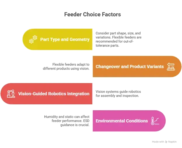
- Part type and geometry, including variability:Flexible-feeding buyers are advised to start with part type and geometry and plan for out-of-tolerance realities.
- Changeover and product variants:Flexible feeders are repeatedly positioned to accommodate product variants on the line, using vision to select pickable parts.
- Vision-guided industrial robotics integration:Our robotic automation solutions page highlights 2D and 3D vision for location and parts assembly, force sensors for difficult assemblies, and vision inspection after assembly for quality assurance, capabilities that directly influence feeder strategy when feeding is vision-guided.
- Environmental conditions, especially humidity and static:ESD guidance stresses that control items must work at the lowest humidity experienced, and that very low humidity conditions are explicitly considered in qualification contexts.
These requirements determine whether the feeder should be optimized for maximum rate (often a traditional feeder), maximum flexibility (often vision-guided), or maximum robustness under environmental variation (often a combination of mechanical feeding plus environmental control).
Feeder Choice Is a Tradeoff between Rate, Robustness, and Adaptability
No single feeder approach dominates across all conditions. The selection is a tradeoff between speed, tolerance to variation, and ability to change quickly without retooling.
| Feeder approach | Strength | Watch-out |
| Vibratory bowl | high sustained rate | static, variation sensitivity |
| Centrifugal | smooth high-speed flow | geometry-dependent |
| Step feeder | gentle handling | lower throughput ceiling |
| Elevator feeder | bulk capacity | orientation limits |
| Flex feeder | fast changeover | rate ceiling |
| Bin picking | minimal tooling | grasp complexity |
| Tabletop shaker + robot | gentle control | throughput cap |
High-volume, stable parts often benefit from dedicated mechanical feeding, while high-mix, variable parts often benefit from vision-guided picking and recipes.
The Six Feeder Types on Norwalt's Page, Reframed For Production Decisions
Norwalt's existing feeder overview lists six common feeder types and explicitly notes that a flex feeder uses vision-guided robots for part selection. The rewrite goal is to retain the recognizable types while describing what causes downtime and what early specs tend to miss.
- Step feeder:Step feeders are typically selected for parts where controlled singulation and gentler handling reduce the risk of damage or misfeeds. Their production risk tends to surface when parts do not seat consistently due to tolerance drift or when the required rate exceeds the stepping mechanism's capacity. The decision point is whether stability and part handling outweigh the maximum rate.
- Elevator feeder:Elevator feeders help maintain bulk supply and reduce refill interventions, but they rarely solve precision orientation issues alone. The risk often shifts downstream: if orientation requirements are tight, additional devices or inspection are needed to avoid doubles or mispresentation. The decision point is whether bulk capacity or orientation accuracy is the main constraint.
- Flex feeder:Norwalt defines a flex feeder as a system that uses vision-guided robots for part selection. This aligns with the trade framing in ASSEMBLY Magazine: vision identifies pickable parts and ignores those that are not pickable, which is a direct mechanism for avoiding classic jam conditions caused by overlap or misorientation. The primary trade-off is between rate and flexibility and tolerance to variation.
- Linear feeder:Linear feeding is often where systems gain or lose stability, as it controls the handoff and buffering between a feeder and a station. Poor transitions create tip-overs, starvation, and collisions even when the primary feeder is "working." While this is less explicitly standardized in a single authoritative document, it is consistent with how feeder systems are described as maintaining consistent workflow in assembly contexts.
- Centrifugal feeder:Norwalt states it has developed a line of centrifugal orienteer-feeders that receive parts in bulk, orient them, and feed them downstream. The decision point is geometry-fit: centrifugal feeding can be smooth and fast for compatible parts, but it is not universal across all geometries.
- Vibratory feeder:Vibratory bowl feeding remains common for stable, high-volume parts, but it has a well-known production risk profile around static and part friction. Ionization guidance explicitly notes that static electricity can be generated by friction of parts conveyed in a parts feeder and that parts can stick to the feeder's surface, recommending blow-type ionizers to prevent sticking.
Norwalt's Feeding Options
These options matter because they address two failure modes that traditional feeders struggle with: high-mix changeover and fragile part handling.
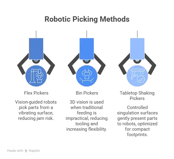
- Flex pickers (vision-guided picking from a vibrating surface): Trade coverage describes the flexible feeding model: parts are presented to a vision-guided robot; cameras image the parts; vision software identifies which parts are pickable; then the robot retrieves the parts for kitting or assembly. This directly reduces jam risk from overlap or misorientation, because non-pickable parts are not forced through tooling.
- Bin pickers (3D vision):Bin picking is used when part geometry or bulk handling makes traditional feeding impractical, and when the business values reduced tooling and higher flexibility. This is consistent with broader adoption discussions in automation industry sources (3D bin picking is deployed across industries specifically to pick parts from random bins and reduce manual handling).
- Tabletop shaking pickers:Tabletop systems are essentially controlled singulation surfaces designed to prioritize gentle handling and controlled presentation to a robot. They are a logical extension of flexible feeding approaches described in trade coverage, optimized for compact footprints and sensitive part handling, with throughput constrained by pick cycle and presentation rate.
What Early Specifications Miss
Feeding problems often surface after early tests pass, because short-duration trials rarely reproduce long-run variability. ASSEMBLY Magazine explicitly emphasizes that real-world part lots contain out-of-tolerance variation and that flexible feeders handle this better than bowls, which is the "production reality" basis for the argument.
A practical implication for buyers is that "it worked in testing" is not a sufficient feeder acceptance criterion. Long-run stability depends on how the feeder handles variance, recovery events, and environmental shifts.
Humidity and Static Are Not Minor Variables
- EOS/ESD Association guidance states that ESD control materials and items used in a facility must work at the lowest humidity level experienced, and references low humidity conditions in qualification contexts.
- NASA ESD control documentation states that surface resistivity changes exponentially with humidity changes and recommends maintaining relative humidity between 40 percent and 60 percent.
- Ionizer technical guidance notes that static electricity can be generated by friction while a parts feeder conveys parts and that parts can stick to the feeder's surface, recommending ionizers to prevent sticking.
These sources support the operational mechanism: low humidity increases static risk and increases the likelihood of sticking or clinging in feeder contexts, and controlled humidity, along with ionization, are standard mitigation levers.
High humidity is also a feeder risk in a different way, especially when parts have coatings or powders. The practical engineering point is that environmental extremes create unstable boundary conditions for feeding, which should be treated as part of system design rather than a shop-floor afterthought.
How Norwalt Connects Feeding Strategy to Real System Performance
Norwalt's feeder article positions feeding as crucial to workflow stability, and its related content highlights feeder variety beyond the six basic types, including custom tray elevator loaders and unloaders, as well as other feeder categories. Norwalt also states that it developed a line of centrifugal orienteer-feeders that receive parts in bulk, orient them, and feed them downstream.
For vision-guided strategies, Norwalt's robotics page explicitly lists 2D and 3D vision, force sensors, and vision inspection after assembly for quality assurance, which are the real building blocks of modern vision-guided feeding and validation.
The practical value to a buyer is straightforward: the feeder strategy is chosen based on part behavior and long-run stability requirements, and then integrated with inspection and robotics capabilities where they reduce real production risk rather than creating complexity for its own sake.
Inputs That Enable Stable Feeder Performance
Feeder performance depends on inputs that reflect production reality rather than ideal assumptions.
- Part samples and CAD, including tolerance ranges
- Surface finish, fragility, and any coatings or powders
- Required feed rate and allowable buffering
- SKU count and changeover expectations
- Expected humidity range and ESD sensitivity
- Cleanliness requirements, especially for medical applications
- Downstream process sensitivity (vision inspection, sealing, marking, assembly forces)
These inputs enable engineering teams to select feeder strategies that hold up when part lots vary and environments shift.
Protect Throughput by Designing for Production Reality
Feeder choice should be an outcome of requirements, not habit.
Feeding problems are often predictable when part behavior, environment, and recovery requirements are treated as first-order design constraints. The most important reason to address these early is that many issues do not reveal themselves during short demonstrations. The long run is where feeding strategies either stabilize throughput or quietly erode it through cumulative micro-stops.
Norwalt's feeder and robotics content makes the intended approach clear: combine appropriate feeding methods, including centrifugal orientation where it fits, and apply vision-guided robotics and inspection capabilities where flexibility and verification reduce real system risk.